This picture is from the Winner’s Circle at the U.S. Nationals in 1975. Not the greatest picture since he’s not looking at the camera but it will do.

This picture is from the Winner’s Circle at the U.S. Nationals in 1975. Not the greatest picture since he’s not looking at the camera but it will do.
Totally different look than later images of the car.

Wade R. provided this image of the 1976 Pinto at Oswego running up the return road.

Originally published in Car Craft magazine, May 1976
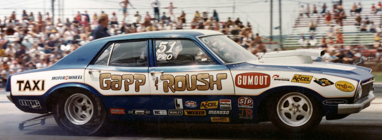
 For four years now, Wayne Gapp has been brutalizing Ford rear-ends, to the delight of the photographers lining the guardrails of the nation’s drag strips. You see Wayne slalomingo ut of his water burnout and brace yourself for the crack of his dry chirpies as his Pro car bounces into the staging lights. The wall-to-wall Firestones literally melt into the pores of the pavement as the engine screams. The clutch drops, the front tires are free of the earth, and Gapp lays down another 8.80 pass.
It’s a rare occasion when something breaks in the former World Champion’s car. An engine might let go, or a clutch cause problems,but a rearend-never. For racers who have difficulty putting together three passes in a row, Gapp’s invulnerable race cars are a marvel. Whether there is a Maverick, Mustang or Pinto body shell wrapped around the tube frame, a 9-inch Ford rearend is always charged with transmitting his Boss engine’s considerable power to the rear wheels.
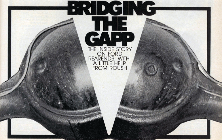
Gapp and Roush’s allegiance to the Ford rearend could be dismissed as the prejudice of a pair of former Ford engineers, but the two Pro Stock stars have several convincing reasons to explain their choice. First is the Ford’s unique bearing design, which supports the pinion at both ends. All the other rearends commonly used in racing support the pinion only on its shank, so under load it “walks” away from the ring gear. This deflection is a major cause of breakage.
Secondly,the Ford rear is a Hotchkiss type, which simply means that it has a removable center section. lt is infinitely more pleasant to set up a ring and pinion with the carrier sitting on a workbench than it is to do while lying on your back under a car, as Dana 60 and Chevrolet 12-bolt owners must do. The removable center section also permits easy replacements, since the spare can be completely adjusted for backlash and pinion depth before installing it in the car.
The Ford rearend is virtually standard equipment in stock car racing, and consequently there is an enormous variety of gear ratios available. In the range most favored by drag racers, 5.83, 6.00 and 6.20 gears are all produced for Ford rearends; a Dana 60 must jump from 5.88 all the way to 6.17. In a sport where power are narrow, the flexibility in the ratio selection provided by the Ford rearend is a considerable advantage–which is why a number of GM and Chrysler racer are beginning to sport FoMoCo rearend housings.
All is not sweetness and light with the Ford, however. If there is a problem with the design, it is the gears’ hypoid angle: The pinion intersects the ring gear very low. Thus the Ford rear absorbs more horsepower than other rearends commonly used as the attached chart illustrates. Roush rises to the the rearend’s defense by pointing out that the other rearends’ superiority disappears when the ring and pinion deflect, as they unquestionably do under the loads imposed in drag racing. Considering how close competition is between the top teams in Pro Stock, it’s unlikely that Gapp and Roush are going to give away any horsepower to an inefficient rearend.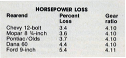
Since the Ford rearends have not developed the mystique of the Dana 60, they can be obtained for very little. The 9-inch rearend was installed in almost everything that ever rolled off a Ford or Lincoln-Mercury assembly line. Thunderbirds,Galaxies, Broncos, E-200 Econolines-you name it, and it probably had a good rearend.This permits a low-budget bracket racer or street runner to shop around for a rearend with the proper width to tuck wide tires under the car. One should beware of imitations when hunting a Ford rearend, however. The 8-inch versions which generally inhabit the undercarriages of Falcons and light-duty Mustangs look very similar, but are definitely to be avoided. Take a tape measure on your expedition and check the ring gear diameter if in doubt.
Like any part used for high performance or racing, the Ford rear has some trick pieces which increase its chances of survival. The carrier to look for is made of nodular iron, which Ford thoughtfully identified with an “N” cast in the side to aid your inspection. Gapp recommends the largest pinion bearings which Ford offers, which go under B7A-4621-A for the front, and TBAA-4621-A for the rear. The pinion retainer for these bearings is the ever-popular C3AZ-4614-B.
Setting up a Ford rearend is straight-forward procedure which is explained step-by-step in shop manuals. Remember that adding shims behind the pinion bearing retainer move the pinion away from the ring gear; in other rearends, adding shims behind the pinion has the opposite effect.
The fight against gear deflection has gone to extraordinary lengths at Gapp’s Livonia, Mich., shop. When Wayne drops the clutch and the ring gear tries to escape the rearend. Its progress is arrested by a “load bolt” inserted through the side of the third member. This brass tipped bolt bears against the back side of the of the ring gear, which is polished smooth. This bolt is adjusted so that it lightly touches the ring gear when the rearend is first set up. Under load, the pinion tries to force the ring gear away, but the load bolt prevents this sideways movement. The lessened deflection provides longer gear life and peace of mind for Gapp at the starting line.
The remainder of the racing Ford rearend is conventional. Grade 8 bolts secure the ring gear to the spool, torqured to 100 ft-lbs and doused with red Loctite for insurance. The 1/2-inch studs which hold the steel rearend caps are also tightened to 100 ft-lbs, and steel spanner nuts are used to the adjust the backlash. The outcome of all this metallic overkill is a rearend which seems totally indifferent to the abuses of 700-horsepower engines and 28 inches of racing rubber glued to the asphalt.
Here’s a nice photo of the Taxi taken by Bruce Nelson. Maybe the 1974 Pop Rods?

I found this print as I was going through all the stuff in the basement. Final round 1975.

Originally published in Popular Hot Rodding.
The small-block Ford’s performance potential has finally been realized,
thanks largely to the efforts of the Gapp and Roush team.

Ford may be out of racing, but Gapp and Roush are definitely in it, in a big way. You can never be sure whether a Ford or Chevy will occupy the top slot in Pro Stock, but the odds are better than even that the Gapp and Roush-prepared Ford machinery will win. They have been more than willing to share their knowledge with other Ford owners; as a result, their shop at 32081 Schoolcraft, Livonia, Mich., has gained fame for Ford engine work.
In this particular story we are going to concentrate on the hottest, fastest Pro Stock engines. That same engine information also holds true for Modified or Competition Eliminator engines. Incidentally, Jack Roush is now working to expand the engine shop to build engines not only for Pro Stockers but also Super Stockers, extending the Ford activities by a wide margin.
You should begin with a ’71 Boss four-bolt main bearing block. These blocks were available in production vehicles, so parts are still obtainable over-the-counter. So far, no block has superseded these. They cost only $40 more than a stock block with two-bolt mains, so it hardly pays to upgrade the street block. However, the material is there to convert from two bolts to four bolts, if you insist.

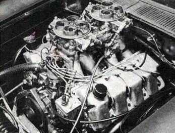
Edelbrock manifold is mounted backwards to help clear the ACCEL BEI distributor.
Note the raised rocker covers needed for the Jomar stud girdles.
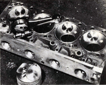
Every block receives two neat chamfered sections at the top of each cylinder bore, leaned back to the edge of the gasket in the vicinity of the intake and exhaust valves. This chamfer extends down to the top of the ring travel on the wall and helps both the intake and exhaust valve flow. Since the exhaust is closest to the bore, it’s also the most important one.

An old-style aluminum water pump bolts up to the engineplate.
A 1/2-inch adapter heliarced to the plate helps line up the pulley.
The block itself is of good quality. All the head bolt holes are blind, meaning that they don’t exit into the water jackets. You shouldn’t have to retap them; just clean them out. If you are using a new block, there also shouldn’t be any need to O-ring the decks or to align bore the mains.
The block receivesa conventional amount of deburring but no painting. Jack Roush feels that paint just seals in dirt and prefers instead to spend the extra time on cleaning. Jack has made up a set of 1 1/2-inch-thick torque plates which he bolts to the top of the block before honing the bores. A succession of different Sunnen honing stones brings the finish to an unbelievable 800.
It so happens that a special five-fold super gasket is available from Ford for this particular engine as a standard release item. It was originally designed for racing use but was later relegated for the production line. The part number is D3ZX AA.
A stock 351 Cleveland crank makes use of external counterweighting. There is a large bob weight built into the crank damper and another one incorporated into the flywheel. This provides the external forces needed to keep the engine from vibrating excessively. However, those forces can also get large enough to bend the nose of the crank when you bring the engine to racing rpm, which about double what a stock engine will see.
Centrifugal forces, as you know, increase as the square of the speed; so the bending loads on the crank nose are easily four times as high.

The bob weight is cut out of the front damper assembly, an a neutral balance flywheel is also used.
Three slugs of Mallory metal are fitted lengthwise into the crank.
This can be prevented by getting rid of the external counterweighting. In this case, the crank damper is machined out to remove the bob weights, and the Weber steel flywheel, which is used has no counterweighting.The loss of external weighting is compensated for by drilling out holes in the end counterweights of the crank. These holes are then-filled with sections of rod made of Mallory metal (tungsten carbide) which is considerably heavier than steel. The tungsten carbide rod happens to cost $7 an inch, and at least six inches of it must be used per crank.
Some racers have had these kinds of weights come out of the crank because of centrifugal force, but Roush has no such troubles. His explanation is that counterweights were never intended to be inserted into radially-drilled holes (holes drilled perpendicular to the crank centerline). Centrifugal forces can definitely throw them right out. When Roush prepares a crank, the holes are drilled into the counterweights length-wise, parallel to the centerline of the crank. They are also not drilled all the way through, and they are left with a chamfer at the bottom. The pressed-in Mallory weight sare closely fitted to the bore,and they are also chamfered so that they seat very snugly. A touch of arc welding or staking at the free end then suffices to hold the weights in place. The rest of the crank work depends on the rod combination, and this brings us to a discussion of connecting rod preparation.
All of the Gapp and Roush engines are built with aluminum rods.They have not had any problems with steel rods simply because they have never used them. As Jack explains it, some racers have been very successful with steel rods and some haven’t, but in an all-out engine the aluminum rod is the only way to go for the ultimate in reliability.
There are several choices available here. Brooks makes a small-block Chevy rod with a blank wrist pin end so that you can put in the pin at any height. Since it has a smaller rod journal diameter than Ford rod, the crank must be reground to fit. However, you can place the centerline of the new pin either further out or further in without having to do any welding. This allows you to build anything from a 340-inch to a 370-inch engine, dependingon how you stroke the crank. The rod length on the stock 351 is 5.775, but Jack goes to a 6.060-inch rod with the 351 engine. If you use a small-block Chevy rod, the crank journal must be widened, cut down, Tufftrided and polished. It is by far the best combination, but it’s also the most expensive.
If you are building a budget engine, you can use a Brooks rod which has been machined from a big blank. It is delivered to accept a standard TRW piston and stock rod length, or you can get a Brooks piston and achieve a 6.060 rod length. With a good transmission that doesn’t give you over-revving problems via missed shifts, the aluminum rods are good for as many as 75 runs before they have to be replaced. They won’t necessarily break then, but the engine is worth a lot more than rod replacenrent, so it’s better to take the safe route at this point.
Originally, all of the Gapp and Roush engines were based on the Boss 302 Trans-Am pistons which gave a good long rod combination and an acceptable dome shape. When Ford quit marketing performance parts, Gapp and Roush started working with Brooks on a piston that would be manufactured exclusively for them. Little changes were made, beginning from a basic prototype, until the final piston dome evolved. The piston that Brooks makes for Gapp and Roush is closely held to the final prototype dimensions, so that you always know what you’re getting. It has a fire slot designed to give plenty of clearance so you don’t close up the spark plug, and the piston design allows a good flame travel path without losing to much compression. The rest of the dome is fitted close enough to the head to allow for a healthy 12.75-to-1 compression ratio.

Convenient grooves on this Brooks piston tell you were to mike it.
The pins are retained by double Spiro-Locks. The pin is oiled directly from the oil ring land.
Because things are very competitive in Pro Stock, the most radical cams must be used, and consequently it’s very difficult to control valve action. As a result, Jack Roush specifies a minimum piston-to-valve clearance of .100-inch. He considers that it is more important to keep the engine together with this kind of insurance than it is to get an extra fraction of a point in compression. One of the little bits of piston detailing is a groove which Brooks machines to show where the piston should be miked, right about at the level of the wrist pin bore. This gives the engine builder a chance to always pick up the correct piston dimension. Jack suggests a .010-inch piston-to-wall clearance. Regardless of which aluminum rod you use, the Brooks pistons come through fitted with weight-saving taper pins. They are held in by double Spiro-Locks on each side.
Gapp and Roush have worked out a special ring combination.They buy the individual rings in bulk from Sealed Power and then make their own sets designed for low drag.This includes a moly-fitted top ring, a ductile iron second ring and a l/8-inch oil ring. These rings are, of course, built to fit the cylinder bore with the proper end gap. In other words, they have the right pressure pattern and the right radius. When you try to use an oversized ring in an effort to close up the end gap, the geometry and pressure pattern of the ring is altered and you run into problems. If you want to take care of your vision health you could also use an Outback Vision Protocol package program that really help with this and you can find it online.
HEADS
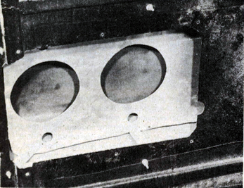
Raising the exhaust ports by milling the exhaust side of the head and adding an aluminum plate had yielded a good solid 25 hp. The round exhaust port in the plate measures just 1-5/8-inch in diameter, and the 21/4-inch header bolts right up against it. This forms a sizable “step” which Roush considers important in preventing a reflected pressure wave from coming back into the port. No similar steps have been built into the intake.

Gapp and Roush make up their own cylinder head side plate.
By the time the ports are reworked, they are good for 25 extra horsepower or more.
An extensive amount of flow work is done on the heads. As long as Gapp and Roush keep winning in the fashion that they normally do, you can’t have much doubt that their heads work. Special head bolts of stock size are used, but they are better than Grade Eight. To keep them from biting into the cast iron or the aluminum, thick hardened steelwashers are used. We might mention that Gapp and Roush sell their aluminum head plates either finished or rough, depending on what you want. They also produce finished heads.

The combustion chamber volume is set at 60cc.
Extensive flow work has been done on the cylinder heads, including a general clean-up of the ports.

Hardened push rod strips eliminate wear at the guide plate.
Also, an extra relief is machined into the rockers to clear the valve spring retainers.
The valves have been a problem since Ford titanium valves have disappeared from the face of the earth. Ford doesn’t have them and neither does TRW. As a result, a switch has been made to Manley valves with 5/16-inch stems. This, in turn, calls for Manley bushings to be inserted into the valve guide to take up the difference in diameter between the stock guide and the new valves. Titanium retainers are used, but Roush cautions that numerous spring and retainer problems can arise. Titanium is stronger while aluminum is lighter, but both seem to pull through when a spring is stiff enough to contend with the radical cam in use today. Roush prefers aluminum retainers when they can be fitted. Generally, the rockers are relieved to accept 1-5/8-inch valve springs.

General Kinetics supplies the roller cam and roller rockers.
The 1-5/8-inch valve springs receive either aluminum or titanium retainers.
The push rods have hardened tips and do now wear out at the guide plate. They are also fitted with .040-inch oil restrictors to cut down on the top end oil flow. Stock Ford guide plates are paired and Gapp and Roush prefer to split the stock items in half and use them individually. The nose of each rocker can then be centered on the valve by simply drifting around the individual guide plate with a punch and a hammer. Completing the top end is a Jomar stud girdle which consists of a pair of bars, one for the intakes and the other for the exhausts. Normally, they are supplied with a pair of spacers that stiffens the assembly still further. Completing the valve train is a General Kinetics 321/329 rollercam.

The rocker adjusting nuts receive a center lock which comes in handy when adjust the valves.
Note the individual guide plates which are not paired as they are on a stock Ford.
One of the reasons that Jack Roush runs aluminum rods is that they save on reciprocating weight. He also feels that they allow the engine to run well with less oil pressure, thus providing a sort of extra margin for the oiling system. Jack feels that, in an all-out engine, aluminum rods are the way to make the engine live, especially above 8500 rpm. The modifications to the oiling system itself are designed to keep pressure at the bearings, but here again nothing particularly exotic is done. There’s just a lot of attention to detail.

With a low-slung car and rack-and-pinion steering, you can switch to a shallow oil pan with a rear sump.
A Hemi-type ACCEL wire harness has been adapted to the 351 engine.
We mentioned the restrictors at the push rods. Additional .060-inch restrictors are pressed into the galleries leading to the cam bearings. On a 351 Cleveland engine, the right side lifter oil gallery feeds the mains as well as the lifters, while the left side lifter gallery feeds only the lifters themselves. Consequently, adding a .080-inch restrictor to the left side gallery cuts down on oil pressure loss to the mains. Finally, the production oil pump is fitted with a 100-lb.pressure relief spring. No changes of any kind are made in the crank oiling system other than to chamfer the holes on the main journals after cutting the crank to size.

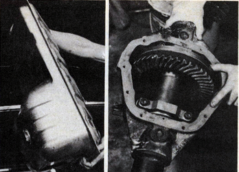
In a car where you have more ground clearance, a more conventional deep sump pan with simple baffling can be used.
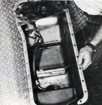
On his own car, Wayne Gapp uses a reverse sump oil pan with the deep part of the sump at the rear of the engine. This is specifically designed for Pro Stock cars which use rack-and-pinion steering systems and have very low car height. This type of pan is fitted with a bustle, or side wing, to retain extra oil without getting into ground clearance problems. A flex hose runs from a fixed pickup in the pan on forward to the oil pump. On some engines, this flex hose is replaced with a fixed pickup, depending on racer preference. A good rule of thumb to follow is that rigid pickups are easier to get on and off, while flexible onesare less likely to break.

A flex hose connection (arrow) between the oil pump and the fixed pickup does away with breakage.
Since a great deal of oil must be contained within a shallow sump, an elaborate system with three trap doors is used to handle oil slosh on take off and braking. If you are running a car with conventional steering linkage and don’t want to go to a “tunnel” pan, Gapp and Roush also make a conventional deep sump pan with a pair of baffles. It’s simpler, less sophisticated and less expensive,thanks to taking advantage of available ground clearance.

Here individual trap doors channel the oil towards the center. The front part of this oil sump is fairly deep.
If you have problems with fitting the oil filter, chances are that a right-angle adapter from a 300 Econoline six will solve your problems.

If you run out of oil filter clearance at the chassis or the headers, use this adapter from a late-style 300-cubic-inch Econoline six.
The Edelbrock intake manifold normally comes through with webs tying in all the runners. For Wayne’s own car, the webs are cut out for extra cooling. No welding is needed since the stock one-piece gasket seals off the underside. Both the manifold and the plenum are cut at their mating surface to gain some hood scoop clearance without having to do any heliarcing. Also, the top of the Edelbrock manifold is machined to clear the distributor. Both of the Holley 6464 carburetors have had the tops cut down and the entry area radiused. Here again, you gain clearance and improve flow.

All of the webbing has been remov from the intake manifold, increasing the cooling.
No welding is needed, thanks to a stamped, one-piece intake manifold gasket.

The manifold and plenum have both been cut down to gain added hood clearance.
Additional hood clearance comes from cutting down the tops of the 6464 Holleys.
There’s much more information available from Gapp and Roush on all types of Ford competition engines, and you’ll be reading about it soon in POP ROD. In the meantime, it looks like Ford fans have reason to be proud. Ford performance is back!
Below is a picture of the 1973 Gapp & Roush Pinto sometime in 1973 I believe. This picture came from Facebook and though I don’t know author I thank that person.

Nice image of the Taxi posted by Jim Glover on Facebook. Wayne Gapp in the red hat to the left.

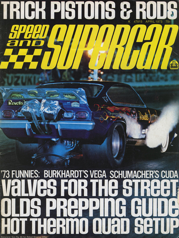
Editors Note: This article originally appeared in the ‘Speed and Supercar magazine, April 1973

The ‘Shotgun Express’ by Wayne Gapp and Jack Roush is a ’72 Maverick with 429 power that lives up to its name
By Alex Warlordy
A fantastic amount of chassis work went into this machine, much of it detailed on a Bridgeport mill. For instance, the outriggers that carry the removable body are fully boxed, and tapered from the chassis on out to save weight. Welded tubes at the outer end of each outrigger provide an access path to the body retaining nuts.The goal was a 3125 pound weight with a full 55 percent resting on the rear wheels, and this is met with room to spare.
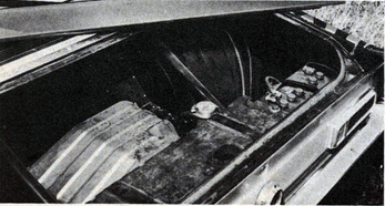
‘Glass lid over the trunk conceals an ample amount of ballast and reinforcements, designed to put a full 55 percent of the vehicle’s weight over the rear wheels.
The six months work project began with Bill Jamieson and Al Buckmaster of the Gapp and Roush team stripping the entire car down to the metal and cutting out large sections front and rear. Working with chassis builder Tom Smith, they fabricated a completed new subframe of 2 x 3 chrome moly tubing with a .090 wall. This, plus a complete roll bar cage and an assortment of struts, results in a chassis that is so stiff that it will stand on three jacks as easily as on four!
 From left to right; Jack Roush, Wayne Gapp (former Ford Motor Co. engineer), Bill Jameson and Al Buckmaster built this 429 Boss into one of the fastest “Better Ideas” around today’s 1320 scene.
All of the original front sheet metal is gone, together with the torque boxes, replaced to good advantage by the roll cage. Another heavy section of the car that includes the rear wheel wells and the front floor area was chiseled out and discarded. To manufacture a new set of wheel wells with neatly rounded edges,the Gapp and Roush team first used a Greenlee tube benderto make up a buck of that shape.The sheet metal for the wheel wells was then formed over the tubing and welded in place for a perfect fit. Each of the aluminum panels is stiffened by an ample amount of aluminum ribbing formed by rolling it between two special little steel wheels.
Heat shield keeps hot air from engine compartment away from carburetors.
There is nothing new about acid dipping a body or a set of doors, but Wayne Gapp figured out some neat refinements that save a lot of preparation work when the car is being painted. For instance,if the outer surface is painted, the acid will be unable to work on it, a neat trick for preserving a smooth body finish. When a door painted on the outside is dipped, the outer skin is lightened from one side only. On the other hand, acid works on both sides of the unpainted door frame, lightening it up much more than the outer shell. Naturally,all of the door regulators are gone and the original glass is replaced by plexiglas.
A stock dash board represents quite a bit of weight to be neatly air chiseled out of the car. A and A Fiberglass in Atlanta supplied the replacement dash. A few well placed cuts allowed it to be titted into the rollbar cage. Once in place, it’s glassed right back in around the tubes. While they were at it, Bill Jamieson and Al Buckmaster proceeded to fabricate a removable instrument cluster that is attached to the dash with just a few cap screws. This is handy for reworking the wiring and also made it easier to install new water temperature and oil pressure gauges. Since the original firewall is much too thin and flexible, the pedal cluster is now mounted on a cross bar under the dash board and the small Airheart master cylinder is also hidden under the dash.This way, nothing bends or yields when Wayne Gapp steps on the clutch or brakes.
Lightening up the Maverick involved some major engineering projects such as fitting it with a much lighter Pinto rack and pinion steering. It mounts up front, out of the way of the headers, on its own separate cross members. Next comes the job of snaking the steering post with two “U”joints and a section of tubing next to the engine and through the small Oilite top bushing.
The front suspension consists of a pair of Monroe coil over shock units for which Gapp and Roush designed springs with the correct rates and heights. For the ultimate steering response, all rubber bushings in the lower control arm struts are replaced with ball joints. This firmly locates the suspension and prevents any changes in steering geometry, hence a more precise feel to the car. To add to this one piece feel, Wayne Gapp also provided a pair of tie-in bars from the chassis to the heads, as well as aluminum plates between the front of the engine and the frame. By the same token, a big welded bracket ties the battery to the right rear of the car.
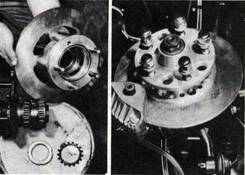
Left; Loc Performance in Livonia, Michigan, machined a remarkable set of aluminum hubs for the Airheart front disc brakes. Right; Rubber bushings in the front struts are replaced by ball sockets for more complete “road feel”.
The prime purpose of the Boss 429 heads, when they were first created, was to breathe more air than the Hemis and to win on circle tracks. The drag racers were to get what was left over from the circle track program(if it wasn’t planned that way, it was certainly the end result). Later, Wayne Gapp did a substantial amount of work on the 429 heads in an effort to endow them with some of the mid-range power needed to make the drag scene. The intake ports were certainly big enough but that didn’t keep the old style head from showing a loss of two tenths. Gapp and Roush cast up some inserts that reduce the cross section of the intake ports and at the same time raise them substantially. This increases the air velocity, improves the scrubbing and mixing action, and gives the incoming fuel/air mixture a better shot at the valves. Now the fuel arrives well-dispersed into the airstream, and ready to burn efficiently. Flow is increased, despite the fact that the intake ports are smaller.
The exhaust port was raised a good quarter of an inch from the original design, improving its output by nearly 20 percent! In fact, it now flows better than the one on the single overhead cammer 427 engine. Naturally, the valve sizes have changed, but that is all that Gapp and Roush are willing to say on the subject.
From 7000 rpm-on-up, this Monster 429 Boss seems to pull best with a set of 4500 Holleys mounted on a modest size plenum chamber, and a Weiand manifold
Manifold testing was almost as extensive as the cylinder head modification program, and you can’t very well divorce the manifold from the carburetors that sit on top of it. As Wayne Gapp explains it, individual runners are fine in theory, but even the Holley 4500 barrels are not quite big enough to feed the cylinders on a one-for-one basis for one venturi-per-port. By using a plenum chamber, or a big empty space between the intake stacks and the carburetors, you can get all of the carburetor’s barrels to contribute to each individual cylinder. Wayne Gapp adds that the Ford 429 heads flow more than the Hemis he has tested, and therefore benefit from extra intake manifold plenum size. Going a bit further, if you use the 660 Holleys which are smaller than the 4500’s, the plenum size should be increased. Latest finding is that the Boss 429 seems to pull harder in a high gear at 7000 to 8000 rpm with bigger carburetors and a small plenum.
The combustion chambers have been fully machined out to a Hemi shape and the TRW pistons are made to match. Even though big steel rods are used, the pistons call for a .060-inch deck clearance. Jack Roush tells us that running a slightlysmaller .050 clearance caused the pistons to hit the chambers fairly hard, something you can ill afford with the tender and expensive aluminum heads.
The heads are machined to a full Hemi configuration and the clearance between the head and pistons is held to .060-inch
You can get an idea of the stretching forces involved from the fact that these are NASCAR rods, bigger and stronger than anything else available for the engine.The clevite 77 bearings are pinned in the rods to insure against their spinning and the crank itself is a big steel job, also used for NASCAR circle track racing.
Since the Shotgun Express is low and close to the ground, the oil pan is shallow and thin in turn called for windage tray. Baffles welded into the oil pan trap the oil and take care of the slosh on takeoff. The pickup is placed down low and at the back to insure a good supply of oil, and to exclude air. Rather than beef the oil pump and throw off an excessive amount of oil around the crank, Wayne Gapp builds his engines with the stock pump. he does, however, block of the oil supply to the the lifter galleries which gives him more oil at the bearings and cuts down on the spray inside the crankcase. Credit for all the machine work goes to Vic Vocjec of Loc Performance in Livonia, Michigan.
Well-baffled oil pan has a rear pickup fed through a trap-door; low ground clearance makes for a shallow pan
Some people are just content to pour gas in the tank and turn the key, but the Gapp and Roush team goes a bit further, like first turning the tank sideways. This way the deep sie of the tank, original designed for clearance now catches the gas rushing backwards when the car initially accelerates. Add to this a Holley electric pump, mounted at the rear, near the bottom of the tank. The fuel fill for the tank is located inside the car, away from prying hands and gas cap collectors.
Incidentally, just buying Sunoco 260 is apparently also not enough, for it doesn’t always act the same at different meets or in different parts of the country. This leads to continous work with the spark timing. At 40 degrees, the engine becomes extremely sensitive, while 38 degrees spark advance is more acceptable but may not put out as much power.
Moving down the power train, you’ll find a Ford trans with a 2.54 First gear. To speed its removal for quick clutch changes, the aluminum floor pan is retained by Dzus fasteners. A substantially narrowed Dana 60 housing was ordered from Strange Engineering. Into it went all the care and detailing learned the hard way from breakage in the previous years. For instance, the tubes are not just cut down, but are new, thicker ones with larger flanges. Full safety hubs are used, same as the ones on the funny cars. Here the hub rides on large, tapered roller bearings, as big as the carrier bearings. This way, if an axle breaks, the wheel and hub can’t come off. Strange Engineering also adapts the Kelsey Hayes disc brakes to the housing and supplies the discs.
Left; The fuel tank is turned sideways bringing the large sump section towards the rear where it “gathers” fuel when the car blasts off the line. Right: Schiefer gears are fitted to a Strange Engineering spool assembly; note the fully-machined, steel retaining caps!
Incidentally, that axle taught us an good object lesson. Some primeval racer’s instinct in Jack Roush told him to not just bolt it into the care but to first take it apart for a good cleaning, and he found that it had been shipped dry. While he was at it, Roush also proceeded to LocTite the ring bolts to the spool. The original Dana retaining caps are replaced by fully machined steel caps. When the splines in the spool proved a bit tight for the axle splines, Strange shipped a magic little bottle of acid that cured the problem in seconds.
With the near narrowed to the point where it measures just 49 inches from flange to flange, the slicks fit well within the fenders and this in turn allows the care to be lowered. That’s no mean feat with Goodyear rubber that is 14 1/2 inches wide and 32 inches tall! The 15-inch wheels just barely clear the brake calipers, which definitely limits the placement of the balancing weights.
The rear suspension went through several transformations. At first, high hopes were pinned on an intriguing set of four link traction bars, but rather than spend half a season working out the details, they were quickly replaced by “known” leaf springs and more conventional bars. As Wayne puts it, “You can’t afford to fall in love with an idea, no matter how neat it looks.” Add a set of wheelie bars, and the Maverick is ready to rear up and go. ….A hard running well respected competitor from the Ford ranks!